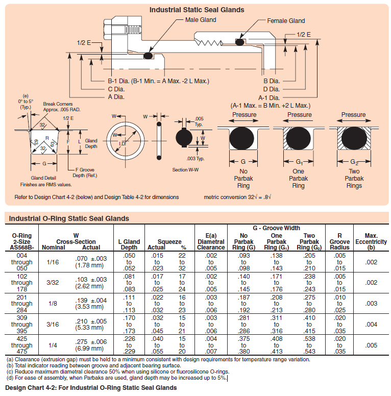
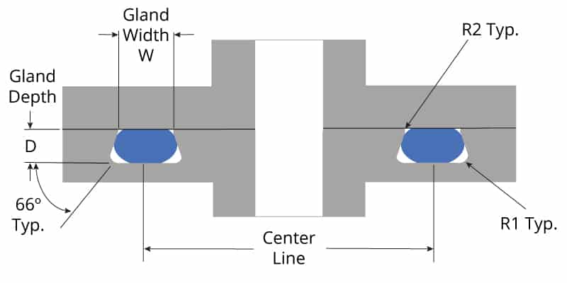
GROOVE DIMENSIONS AND MACHINING CONSIDERATIONS Example of Determining Groove Dimension Determine the appropriate groove dimensions and tolerances for the following seal Reciprocating seal, OD sealing Size 214 0Ring Solution PISTON GLAND PISTON GROOVEÐIA ROD GLAND B RODOD, MIN MAX—2 L MAX) C PISTON 00 A CYLINDER BORE DIA D RODRing g 63 32 16 r gland detail break corners approx 005 rad 0° to 5° (typ) l groove depth 1/2 e g 63 32 32 r gland detail break corners approx 005 rad 0° to 5° (typ) l groove depth (radial) 1/2 e pressure g one backup ring pressure g two backup rings sm o rings width id sm 3 15 ±01 25 ±015 sm 4 35 ±015 sm 5 45 ±0ORing Size Chart and Installation Data References AS568A Uniform Numbering System 005 MAX 003 MAX See groove width dimensions below Selection and Size UNIVERSAL SERIES AS568A DASH NOS SIZE CHART INSTALLATION DATA GROOVE DIMENSIONS OD SEALING RECIPROCATING SEALS ID SEALING ROTARY SEALS ID SEALING OD SEALING STATIC
Sae J1453 O Ring Face Seal Groove Size Chart Knowledge Yuyao Jiayuan Hydraulic Fitting Factory
How to calculate o-ring groove dimensions
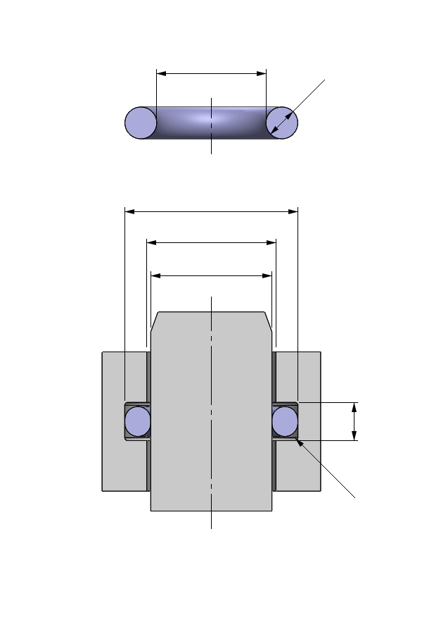
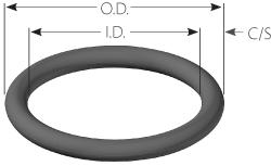
How to calculate o-ring groove dimensions-14 Oring Size Charts Note The AS Oring Size Chart has a column that shows the Nominal Size alongside the Actual Size Originally the nominal size was just for a listing of the approximate fractional dimensions of the Oring Prior to the common use of dial calipers many people called out a 1 inch by 11/4 rt = Oring, this was a dash 214An Oring seal is used to prevent the loss of a fl uid or gas The seal assembly consists of an elastomer Oring and a gland An Oring is a circular crosssection ring molded from rubber (Figure 11)


Www Hitechseals Com Includes Pdf O Ring Brochure Pdf
ORing Reference AS568 Sizes AS568 ORing Size Reference Freudenberg and NOK Group 1 The Simrit ORing Design Quick Reference This design quick reference guide is intended for use in specifying Oring and groove dimensions for static applications with pressures less than 1500 psi The guidelines are for the nominal condition The minimumDimensions of ORings in one ordering number How to Determine ORing Size* For Sequence in Ordering 1 Size (catalog number) 2 Durometer and material 3 Quantity Example 110 – 70SLR – 10,000 (size – durometer, material and color – quantity) Outside diameter (OD) is for reference only ORings are specified by ID and cross sectionBe it dynamic or static operation, radial or axial loading, vacuum or high pressure
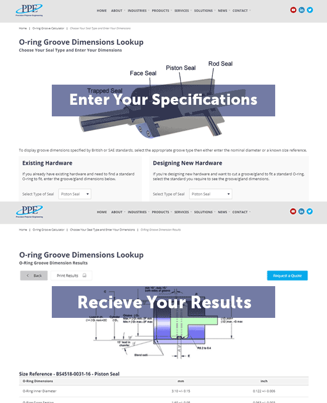
Second Pick the series Oring desired, based on the thickness of the flange available to cut the groove depth desired (I244) Third Check the swell characteristics of the fluid on the rubber to determine whether the normal or high swell chart will be used for dimensions of the Oring groove (In this case 015% or normal swell Chart I)The ORing Store LLC ORing Groove Chart ORing Cord Stock OSK™ Assorted ORing Kits OSK™ ORing Repair Kits OSK™ Hydraulic Seal Kits OSK™ Air Nailer ORing Kits ORing Lube ORing Tools AS568 ORings (Inch) Metric ORings (mm) OSK Pool, Spa & Pump Orings Hydraulic Seals Inch ORing Glue & Thread Sealant Vulcanized ORings ORing Splice Kits & ToolsThe Oring groove calculator enables engineers to specify an Oring groove for any given Oring or vice versa calculates the best suitable size Oring for any given groove The calculator takes all relevant parameters into account like ORing squeeze Free groove volume ORing inner diameter stretch, outer diameter squeeze
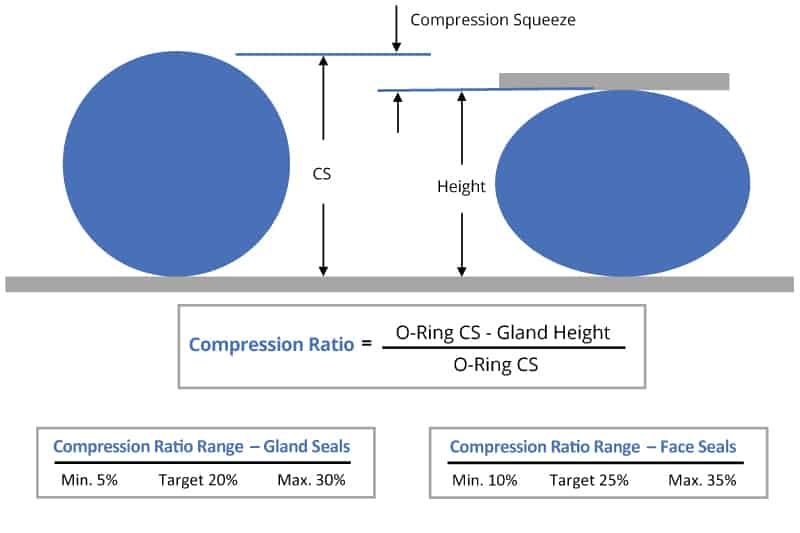
Chart 50 inch & metric sizes 1316 'O' rings for pipe fittings 16 Aerospace sizes to BS ISO 17 Chart 72 metric sizes 2122 Chart inch sizes 23 Nonstandard sizes 24 Complementary products Coloured materials 25 'O' ring cord 25 Commercial quality 'O' rings 25 'O' ring kits 26 Special packaging & kits 26 'OORings Dimensions & Illustrations wwwPrecisionAssoccom In order to assure size accuracy, make sure that Page Scaling is set to NONE prior to printing this document Change this setting by selecting File, Print Page Handling Page Scaling None After printing, verify that size is correct by chec king scale on printed pageThe ORing should be installed in a groove in the body, the depth of the groove should be such that the ORing projects a little above the groove When the shaft or the rod is mounted, the ORing will be compressed by 1015%, so that an effective amount of sealing will be obtained C The application of ORings for sealing rotating parts is not


Www Hitechseals Com Includes Pdf O Ring Brochure Pdf


1
Oring installation dimension Please choose the particular value/measurement in the according box You can choose either a special cross section, groove depth or groove width All other parameters will be generated automatically All data in millimetre Errors and amendments accepted The declared values are not binding and can not be contestedMETRIC IMPERIAL IMPERIAL BS Reference Alternative References ID Section OD ID Section OD ID OD BS 54892 Parker Hannifi n Corporation • ORing Division 2360 Palumbo Drive, Lexington, KY Phone (859) † Fax (859) wwwparkeroringscom Sizes Parker ORing Handbook Sizes


The Parker O Ring Selector Easy Fast And Reliable Selection Of O Ring Materials And Sizes In A Single Application
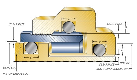


Groove Design O Ring Seals Minnesota Rubber Plastics
The following table shows the groove dimensions for QuadRings®/ XRings • If ®the QuadRing/XRing swells in the application, the groove width can be enlarged up to 15% max • For ®the QuadRings/XRings not listed, the groove dimensions are available upon request Table AS8A Gland Dimensions (millimeters) QuadRingAnd within the groove on the pipe exterior should not exceed 0010"/025 mm † On roll grooved pipe, Allowable Pipe End Separation and Deflection from Centerline will be ½ values listed for cut grooved pipe For 14 – 24"/350 – 600 mm roll groove dimensions, request publication 2509 COLUMN 1 Nominal IPS Pipe sizeO Ring Groove Design Chart GGroove Width CrossSection Gland Squeeze Diametral No Backup One Backup Two Backup Groove Normal Actual Depth Actual % Clearance Ring (G) Ring (G1) Rings G2) Radius 070 050 015 22 002 093 138 5 005 1/16 003 to to to to to to To to
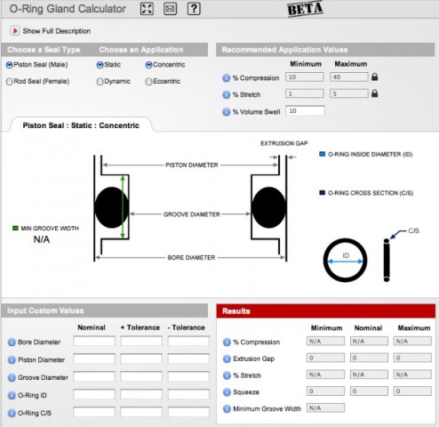


New Gland Calculator Tool At Applerubber Com Official Apple Rubber Blog


Z98 D1xd2 O Rings Redirecting And Seal Cooling System Z Product Catalogue Hasco Portal
901 3/32 902 1/8 903 3/16 904 1/4 905 5/16 906 3/8 907 7/16 908 1/2 909 9/16 910 5/8 911 11/16 912 3/4 913 13/16 914 7/8 916 1 918 11/8 9 11/4 924 11/2 928 13/4Metric ORing Size and Standard Sizes Chart (PDF) ORing Standard Size (AS 568A) ORing Standard Size (BS 4518) ORing Standard Size (GB/T ) ORing Standard Size (JIS B 2401) ORing Standard Size (Metric) ORing Standard Size (Swedish SMS 1586) XRing Standard Size Backup Ring Standard SizeOring groove design guides offer default dimensional guidance on the most basic oring groove design applications The best orings are useless without the right groove design which becomes increasingly important the more demanding the application environment Compare ORing Sizes USA AS568 Parker ORing Size Chart, XRing Square Ring Size


Www Hitechseals Com Includes Pdf O Ring Brochure Pdf


Metric O Ring Groove Design Reference Guide
Dimensions of orings in one ordering number How to Determine ORing Size* For Sequence in Ordering 1 Size (catalog number) 2 Durometer and material 3 Quantity Example 110 – 70SLR – 10,000 (size – durometer, material and color – quantity) Outside diameter (OD) is for reference only ORings are specified by ID and cross sectionFree Diameter & Ring Dimensions Housing Diameter & Groove Dimensions Snap Ring, Internal, Metric Flat Wire Once installed in the groove of a housing/bore, the portion of the ring protruding from the groove holds an assembly in place 138 For the most uptodate specifications, online ordering, quotations & sample orders, visitwwwrotorclipcom h Groove style B i Screw threads SAE J1453 ORFS Groove and orfs o ring sizes chart as follows Dimensions in millimetres Oring Surface B d f i 1 i 5 d 4 Tube outside diameter Thread a Outside diameter Inside diameter nom tol ± 0,4 min nom tol min max 6 9/1618 UNF 2,4 ± 0,3 10 9 7,65 ± 0,16 11,08 6,1


Sae J1453 O Ring Face Seal Groove Size Chart Knowledge Yuyao Jiayuan Hydraulic Fitting Factory
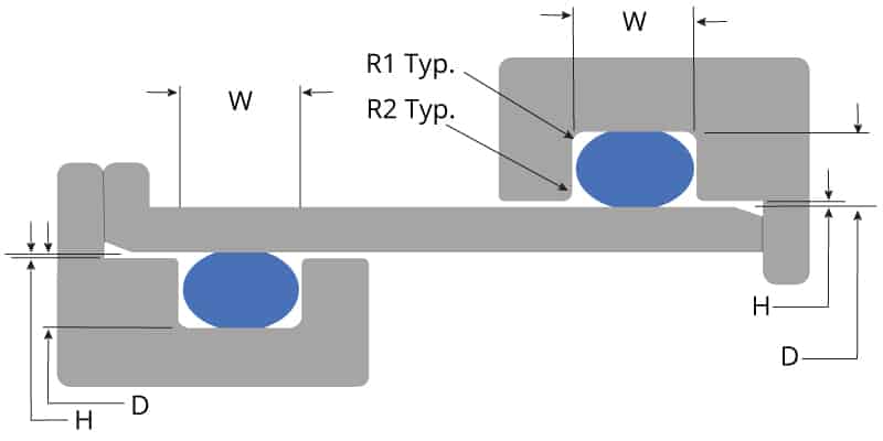


O Ring Groove Design Global O Ring And Seal
British Standard BS ORings Size Chart Standard British ORings sizes Tolerances vary by use, please see out tolerance pages Thousands of nonstandard sizes are available in stock or can be made within a few weeks typically without tooling fees so no need to settle for aThis metric oring groove design reference guide will help you find the right radius, backup, pressure and other oring dimensions for basic applications Once you find the exact metric oring you need, you can easily order online from the world's largest oring inventory network ORing Size Charts Oring, xring and square ring size chartsHQ, EXPORTS CENTRAL WAREHOUSE Reginald Road, Smethwick, West Midlands, B67 5AS Tel 44 (0)121 429 8011 Fax 44 (0)121 434 3016 sales@barnwellcouk / export@barnwellcouk


Sae Flange O Ring Code 61 Dimension Charts Knowledge Yuyao Jiayuan Hydraulic Fitting Factory


Jis O Rings Size Chart Rubber Shop
ORING REFERENCE AS568 SIZES 1 Oring tolerance stackup) and the smallest possible Oring in the largest possible groove specifying Oring and groove dimensions for static applications with pressures less than 1500 psi The guidelines are for the nominal condition The minimumC24 ORing dimensions for straight thread tube fittings in accordance with AS 568 C25 ORing dimensions for metric thread with conical recess in accordance with ISO 6149 C26 Preferred metric ORing dimensions C3 ORing Seal Sets ORingmetrisch_15indb 3O'ring Groove Design As important as the o'ring seal itself is the groove that the o'ring seats into The groove must be designed to accommodate not just the o'ring size, but also its intended usage;
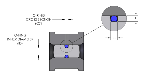


O Ring Groove Design O Ring Groove Dimensions Mykin Inc
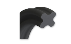


O Ring Size Chart For U S Metric Standard Sizes
2) If for some reason the 'O' Ring is missing and all you have is the shaft, rod, piston or housing, often referred to as 'the metalwork', then you can use the application descriptions on page 5 and the groove dimensions on pages 30 and 31 to decide what is the closest size 'O' Ring, again bearing in mind the points made in section 1Size Chart PDF Available ORing Tooling Sizes AS568 is the Aerospace Size Standard for Orings from the Society of Automotive Engineers SAE Aerospace Standard (AS) specifies the inside diameters, crosssections, tolerances, and size identification codes (dash numbers) for Orings used in sealing applications and for straight thread tubeDimension the groove by it's ID and width Hi=Mean ID of Oring Tol=1% of Mean ID Not > 060 Face Seal Gland These dimensions are intended primarily for face type seals and low temperature applications W L G R ORing ORing Groove Width Size Cross Section Gland Squeeze Vacuum Groove
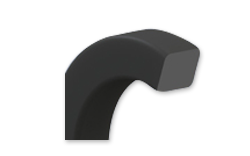


O Ring Size Chart For U S Metric Standard Sizes


Projects Iq Harvard Edu Files Epm Oring Handbook Pdf
An Oring is a solidrubber seal shaped like a doughnut or torus When compressed between mating surfaces, an Oring blocks the passage of liquids or gases Parco Orings are available in a wide range of standard and nonstandard sizes that are suitable for nearly all sealing applications Two dimensions describe the size of an Oring itsCommon Metric ORings Sizes Tolerances var y by use, please see our tolerance pages Thousands of nonstandard sizes are available in stock or can be made within a few weeks typically without tooling fees so no need to settle for a less than optimal fit Size CS (IN) ID (IN) OD (IN) CS (MM) ID (MM) OD (MM) 05X13 00 0051 0091 050 130 230If you need to know how to size an Oring, consider starting with these AS568 Oring sizes so you will not have to purchase custom Oring sizes which can be more costly This AS568 Oring chart is a SAE size standard for Orings and shows AS568 Rev B or AS568B Oring sizes which supersedes AS568 Rev A or AS568A Oring dimensions


1
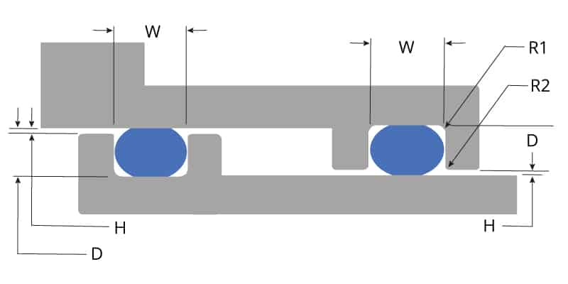


O Ring Groove Design Global O Ring And Seal
SIZE ID CS ID ± CS ± ID ± CS ± SIZE AS568 Dimensions AS568 is the Aerospace Size Standard for Orings from the Society of Automotive Engineers Simrit manufactures and supplies the complete range of standard AS568 sizes in a wide range of elastomeric Oring materials The following sizes are grouped by crosssection andLip design, while still being able to replace orings without changing the groove The Standard ORing Loaded UCup profile is square in cross section and it is suitable for both rod and piston applications The Standard design can be widely used to replace existing hydraulic packing and ORings without changing gland designThe Oring to roll slightly in its groove under certain conditions of motion, but the rolling action is not necessary for normal operation of the seal The shape of the groove is unimportant as long as it results in proper squeeze of the Oring Groove dimensions are


Dovetail Cutters Destiny Tool
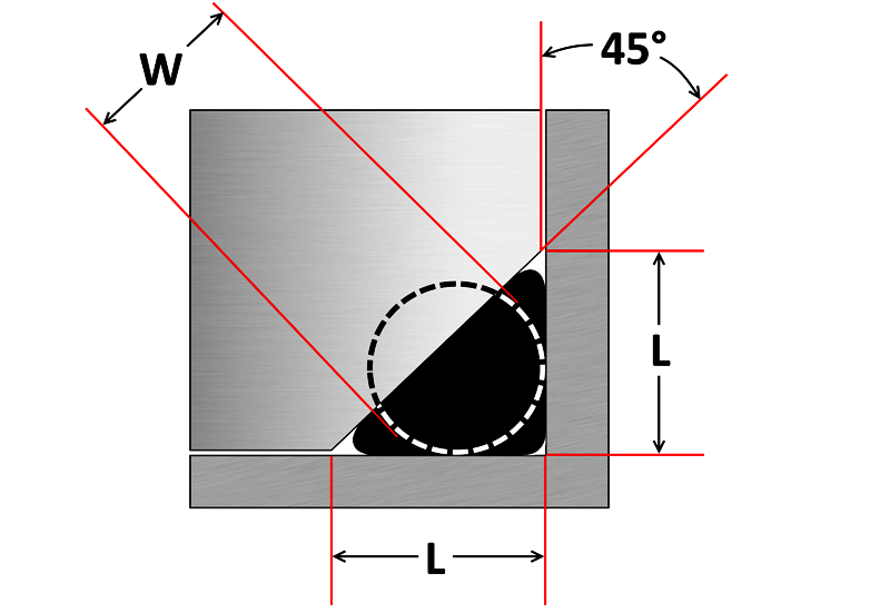


O Ring Groove Design Sealing Australia
On Oring drive belts and their application will be found in ORing Applications, Section III 12 What is an ORing Seal?ORING REFERENCE AS568 SIZES 1 THE FREUDENBERG–NOK SEALING TECHNOLOGIES ORING DESIGN QUICK REFERENCE This design quick reference guide is intended for use in specifying Oring and groove dimensions for static applications with pressures less than 1500 psi The guidelines are for the nominal condition The minimumUS and Metric ORing Sizes, QuadRing Seals, Rubber XRing Seals, Rubber SquareRing Seals The proper oring size is a fundamental aspect of proper oring performance Whether your application conforms to US, Japanese JIS, British BS, or Common Metric sizing for orings, these oring size charts will help you locate the right oring size
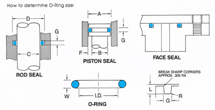


O Ring Groove Design


O Ring Groove Design Global O Ring And Seal
ORing Components Castable Male overdenture pattern o 52mm height, may be reduced to 25mm o mm Ø Metal Housing (#3) o mm height o 52mm outer Ø ORing Overdenture Paralleling Mandrel One per package Black ORing OSO ORing size chart available o ORing insertion Tool For #2, #2M, and #3 Orings ORing Overdenture Analog One per packageMS ORING CHART SIZING (IMPERIAL SIZES) Part No marked in red are stock lines EMail sales@asapsparescomau Where Good Old Fashioned Service & Loyalty still Prevails Catalogue Index Our Part No ID OD Width Our Part No ID OD Width MS 15/8 113/16 3/32 MS 1/4 1/2 1/8An Oring, or toroidal seal, is the most common type of seal used in the world today Used to form a physical barrier to prevent the mixing of gases or liquid fluids, the simple toroidal shape of an Oring has proven to offer high sealing efficiency across a wide range of applications
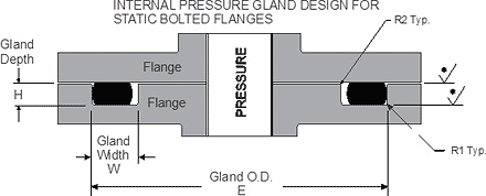


O Ring Static Face Seal Groove Design Guide


Newdealseals Com App Uploads 04 Newdealseals O Ring Handbook 14 Pdf
JIS B 2401 ORING SIZE CHART 1005 Warner Ave, Suite A Lewiston ID 501 Phone (8) Fax (8) The Japanese Industrial Standard (JIS B 2401) lists 194 sizes of Orings which are unique to Japan's automotive and manufacturing industries JIS ORings consist of 4 series of sizes for different applications These series include;AS568B STANDARD ORING GROOVE DESIGN Contact Us For Assistance Or Samples Click Here and contact us today to receive a quote or if you have any questions regarding sizing × Dismiss alert The three main types of standard groove designs are Industrial Static also called Radial, Industrial Reciprocating also called Dynamic, and Face Seals alsoStandard ORing Sizing Chart ORing Size # Actual ID Inches Actual CS Inches Nominal Reference ID Nominal Reference CS Nominal


4000 Series O Ring For Sae J 1926 2 3 Stud Ends Air Way Manufacturing


O Ring Groove Design Standard As568b Seal Design Inc
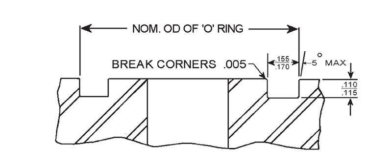


Sae J518 O Ring Assortment Kits On Anchor Fluid Power
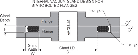


O Ring Static Face Seal Groove Design Guide


Designing Axial Static O Ring Grooves To Industry Standards Grabcad Tutorials


O Ring Calculator Ceetak Sealing Solutions


Newdealseals Com App Uploads 04 Newdealseals O Ring Handbook 14 Pdf


V Ring Seals Seal Design Inc


Http Practicalmaintenance Net Wp Content Uploads Working Design Considerations And Maintenance Of O Rings Pdf


O Ring Groove Design Guides Engineering Quick Reference


O Ring Groove Design Global O Ring And Seal
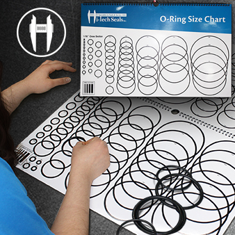


Accessories Measurement Tools


Buna O Ring O Ring In Houston And Minneapolis Dichtomatik


O Rings And Back Up Rings Skf Skf


Http Www Allsealsinc Com Parcoo Ringsizechart Pdf
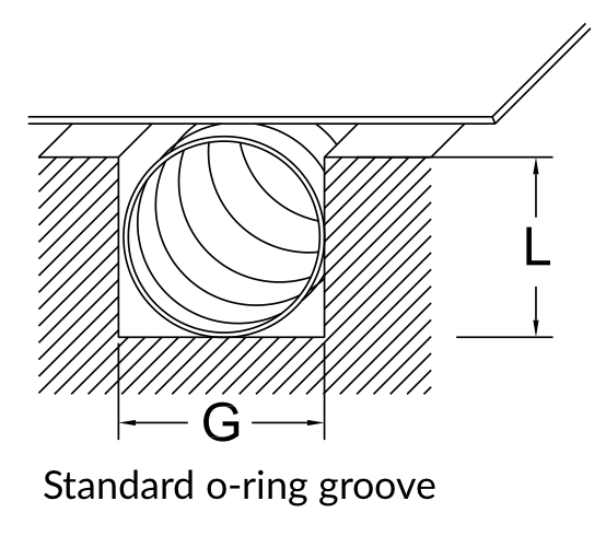


Spira Shield Spira Manufacturing


Sae J1453 O Ring Face Seal Groove Size Chart Knowledge Ever Power Group Co Ltd
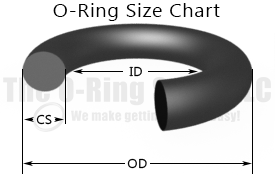


O Ring Size Chart The O Ring Store Llc We Make Getting O Rings Easy
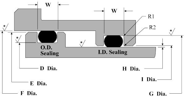


Dynamic O Ring Design Chart Marco Rubber Plastics Custom O Rings Supplier


O Ring Groove Dimensions Calculator Precision Polymer Engineering


Mating Ring An Overview Sciencedirect Topics
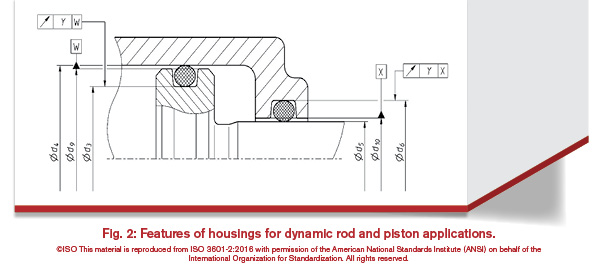


History Of The Iso 3601 Series Of Standards For O Rings Fluid Power Journal
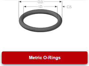


Custom Metric O Rings Metric O Ring Seals Standard Metric O Rings
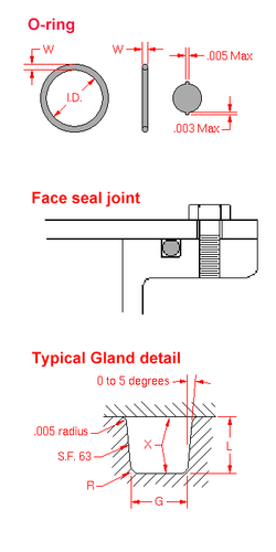


O Ring Wikipedia
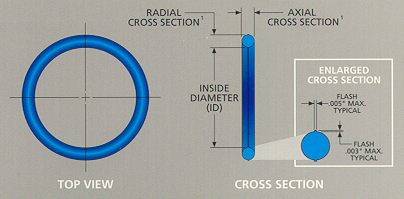


Learn How To Measure O Rings The Right Way O Ring Size Chart


O Ring Sizes And Dimensions Seal Design Inc


O Ring Size Chart Pdf Sae O Ring Size Chart


O Ring Groove Design Metric Seal Design Inc


Oring Ehandbook
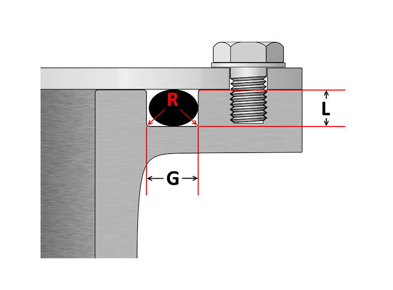


O Ring Groove Design Sealing Australia
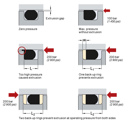


O Rings And Back Up Rings Skf Skf


O Rings An Overview Sciencedirect Topics


How To Calculate The Right O Ring Size With The Parker O Ring Selector
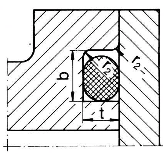


O Rings Allied Metrics Seals Fasteners Inc


Sae Code 61 O Ring Groove Dimensions Knowledge Yuyao Jiayuan Hydraulic Fitting Factory


Great Resource For Designing With O Rings Inventor Tales


O Ring Cross Section O Ring Groove Design Data


O Ring Groove Dimensions O Rings Cords And O Ring Boxes Tiivistekeskus


O Ring Groove Design Guides Engineering Quick Reference


O Ring Groove Design Overview Engineering Guide
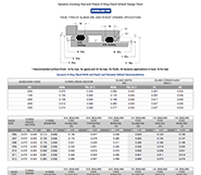


O Ring Groove Design Guides Engineering Quick Reference
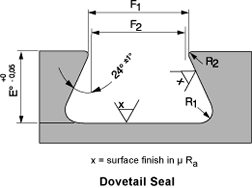


Standard Dovetail Grooves Dovetail Groove Engineering Design Guide
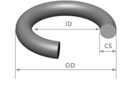


British O Ring Size Chart Bs British Standard O Ring Sizes
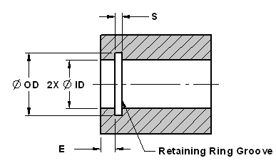


Internal Retaining Snap Ring Sizes And Groove Design Chart Engineers Edge
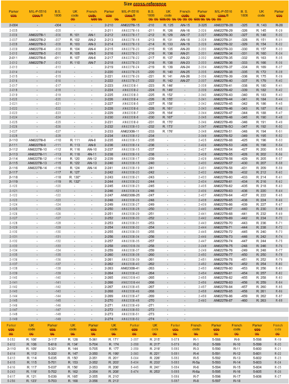


11 Standardisation O Rings Stock O Ring Webshop


O Ring Groove Design Standard As568b Seal Design Inc


Quad Rings All Seals


Jaso O Rings Size Chart Rubber Shop
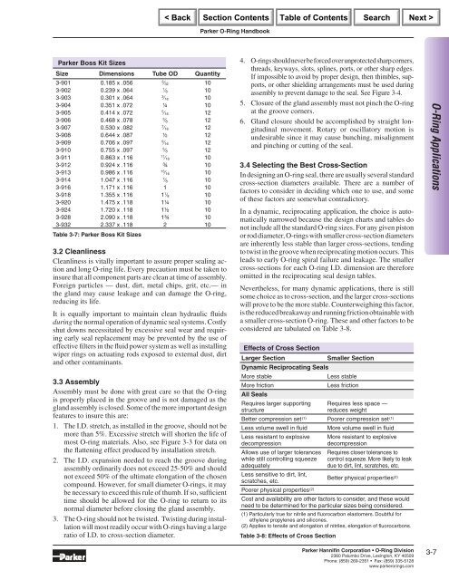


O Ring A


Www Trelleborg Com Healthcare Media Tss Media Repository Healthcare And Medical Pdfs O Ring Gb En Pdf Rev Ad60cc2e6bf84a0eaaebeaa9d3 Hash F17dcfe5190b79c85d7f
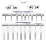


O Ring Groove Design Guides Engineering Quick Reference
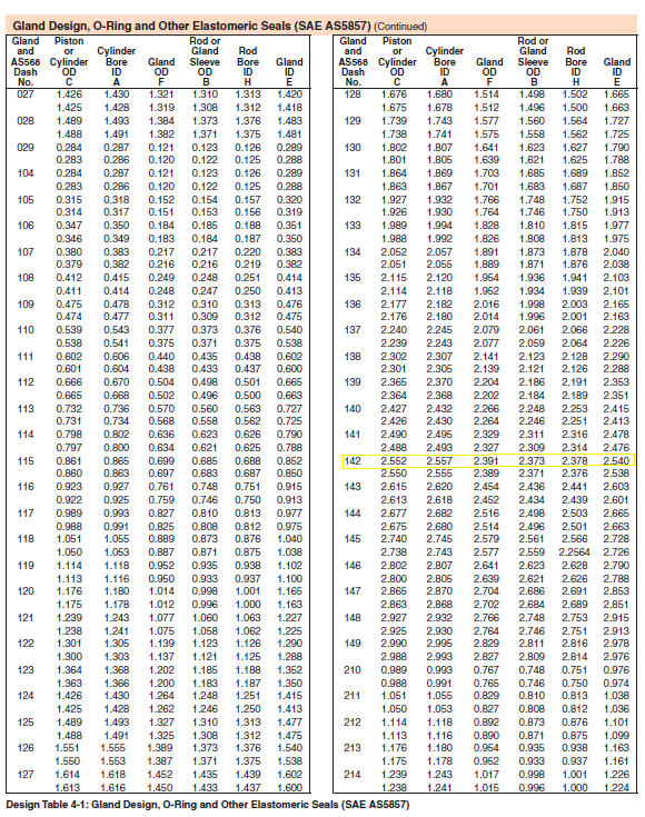


Designing Axial Static O Ring Grooves To Industry Standards Grabcad Tutorials
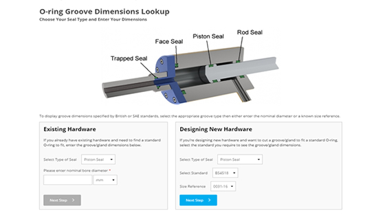


O Ring Groove Dimensions Calculator Precision Polymer Engineering


Http Www Allsealsinc Com Parcoo Ringsizechart Pdf
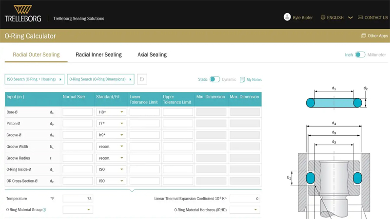


O Ring Calculator Trelleborg Sealing Solutions
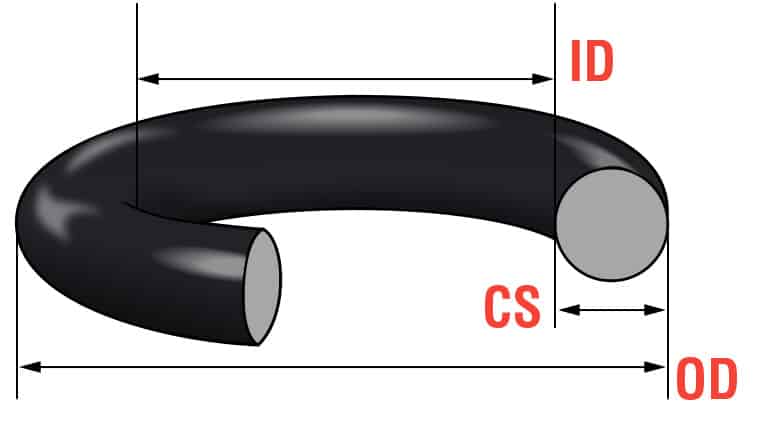


O Ring Size Charts As568 Metric Global O Ring And Seal


Http Www Allsealsinc Com Parcoo Ringsizechart Pdf
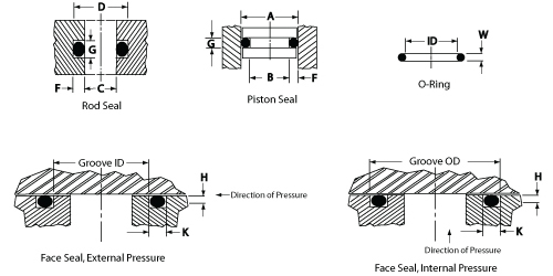


O Ring Groove Design Daemar Inc


O Ring Groove Design Standard As568b Seal Design Inc


Quad Rings All Seals


O Ring Size Chart Rubberpartscatalog Com


Custom Metric O Rings Metric O Ring Seals Standard Metric O Rings


O Ring Groove Design Global O Ring And Seal


O Ring Grooves


O Ring Groove Design Global O Ring And Seal


O Rings P Series Misumi Misumi Misumi


1


1


O Ring Groove Dimensions Calculator Precision Polymer Engineering


How To Use An O Ring In A Non Circular Groove Pattern
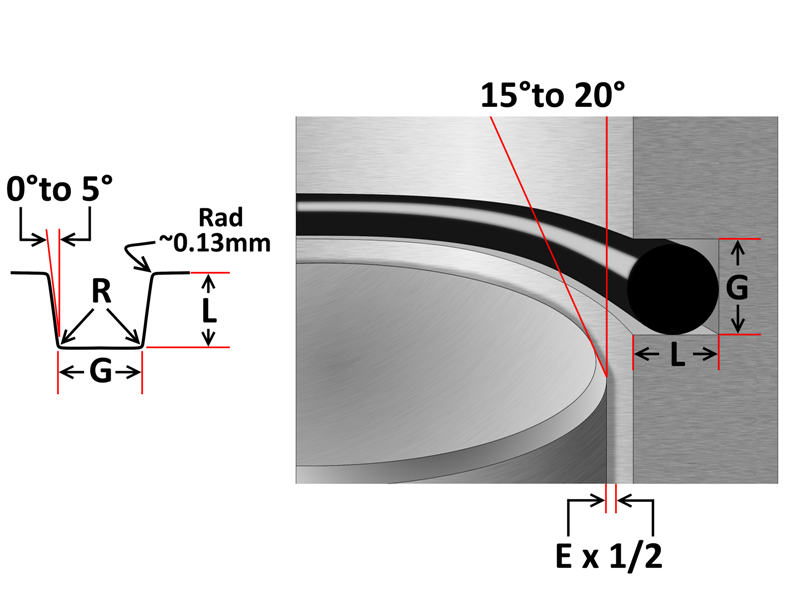


O Ring Groove Design Sealing Australia


History Of The Iso 3601 Series Of Standards For O Rings Fluid Power Journal


O Ring Size Chart Rubberpartscatalog Com


Www Trelleborg Com Healthcare Media Tss Media Repository Healthcare And Medical Pdfs O Ring Gb En Pdf Rev Ad60cc2e6bf84a0eaaebeaa9d3 Hash F17dcfe5190b79c85d7f
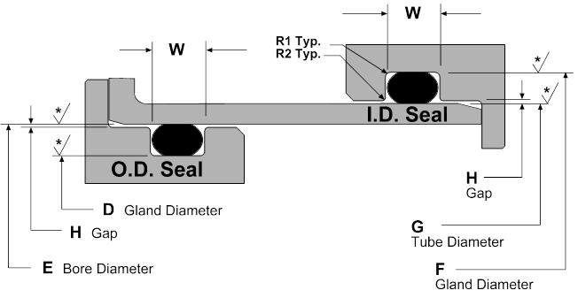


Static O Ring Design Chart Marco Rubber Plastics Custom O Rings Supplier


O Ring Grooves


Buna O Ring O Ring In Houston And Minneapolis Dichtomatik
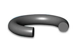


O Ring Size Chart For U S Metric Standard Sizes


O Ring Info En O Ring Technical handbook 14 eriks nv o Ring technical handbook o Ring gland design new Pdf


Buna O Ring O Ring In Houston And Minneapolis Dichtomatik


